Match To Live Action
This project is an introduction to integrating computer generated images with Live Action photos. The goal is to create and "match" a cg object to that of a real object in a photo that I have taken. In seeing the complexity of matching the lighting of a CG object to that of the real world, I will develop a finer grasp of lighting tools and the need for attention to detail. Emphasis is on capturing and replicating bounce light.
Breakdown
Step 1: Photography
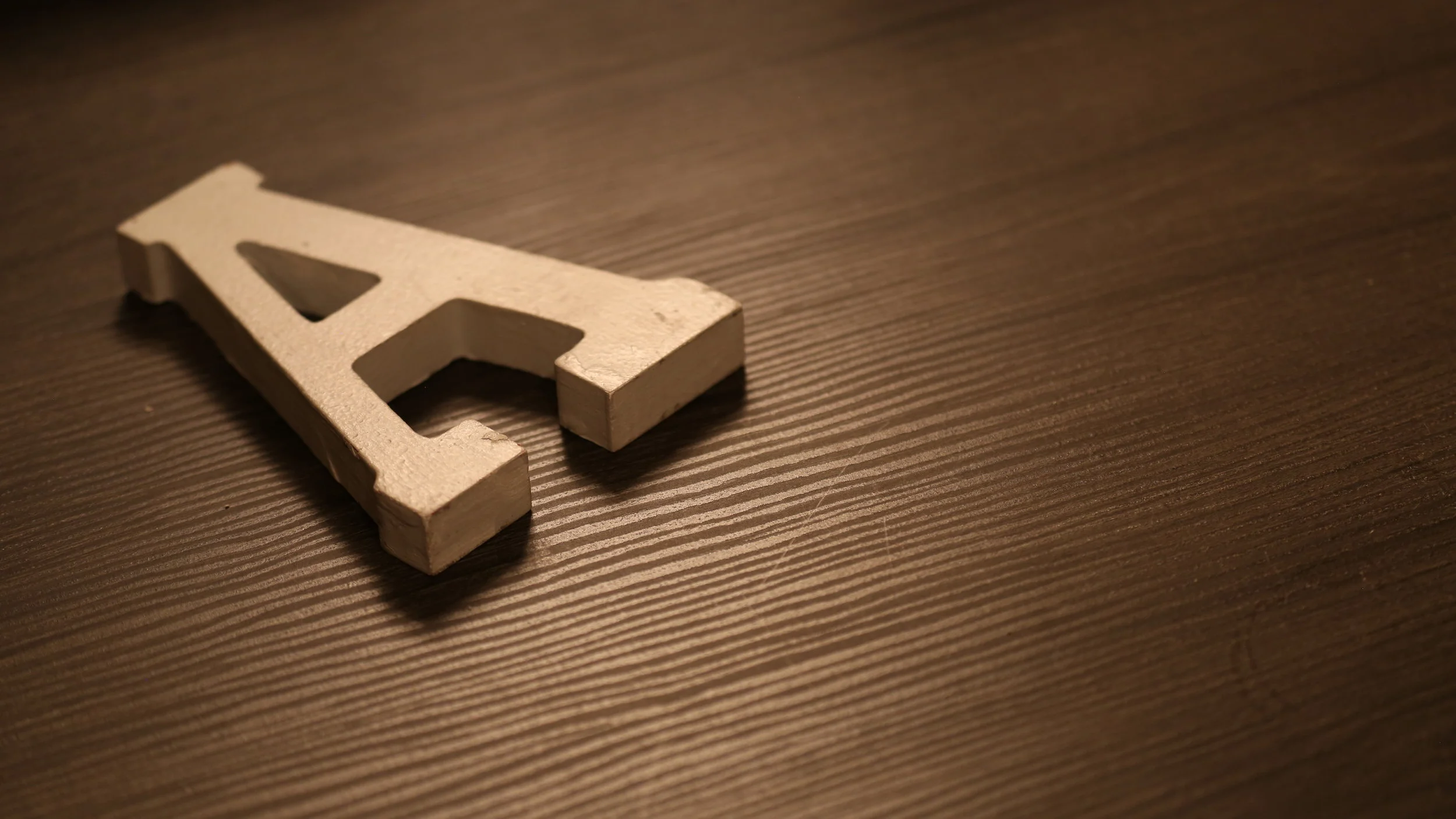
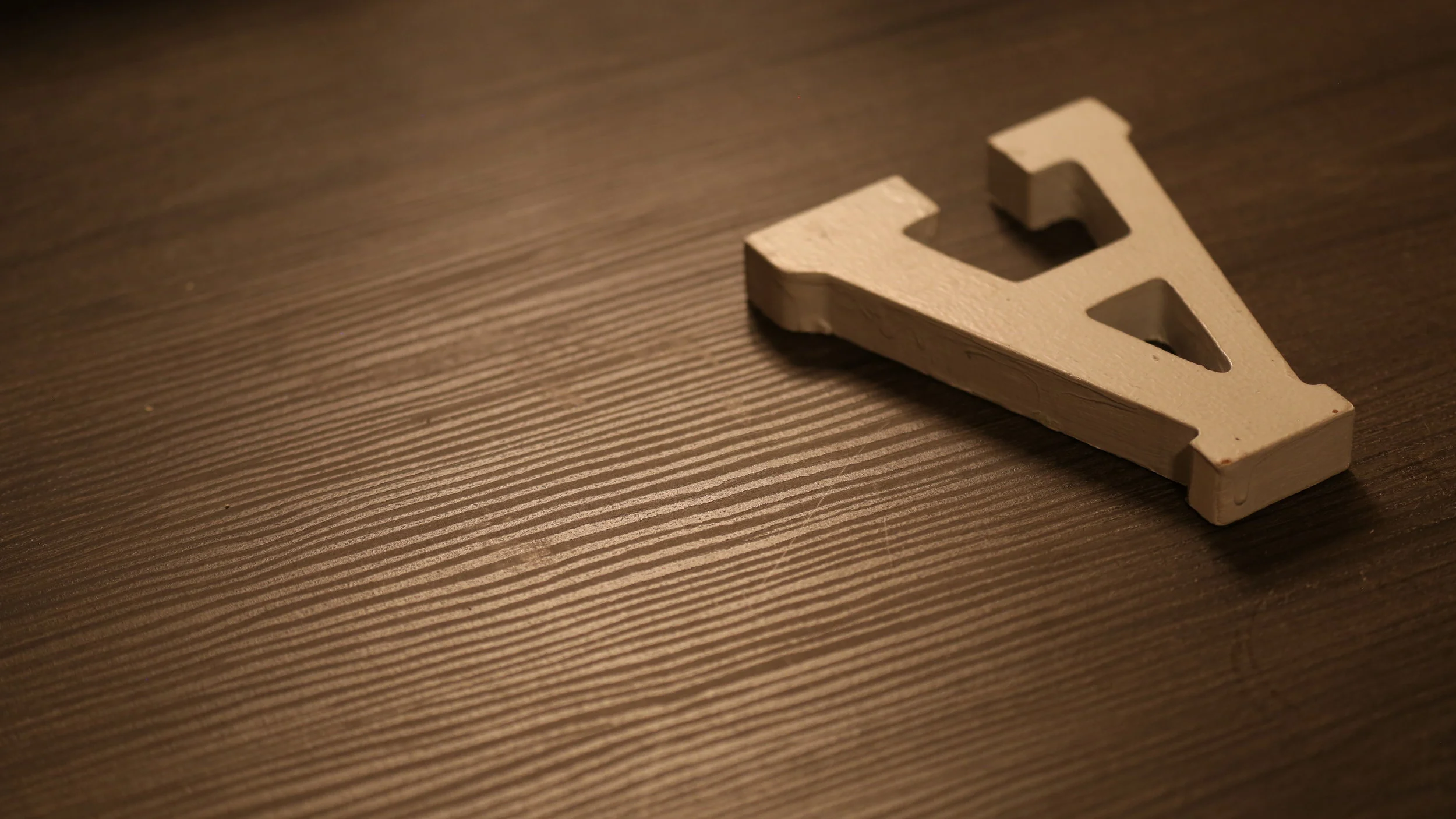
The first step of this project is to take a series of photos of the real object that I chose in a variety of settings and lighting. The goal is to make the photos interesting and have a clear focus on the object and the space where the twin will be. The real object should take up 25% of the pixels on screen, and leave room for a CG twin to be included at about the same size as the original. Bounce light between the object and the surface that it sits on should be evident.
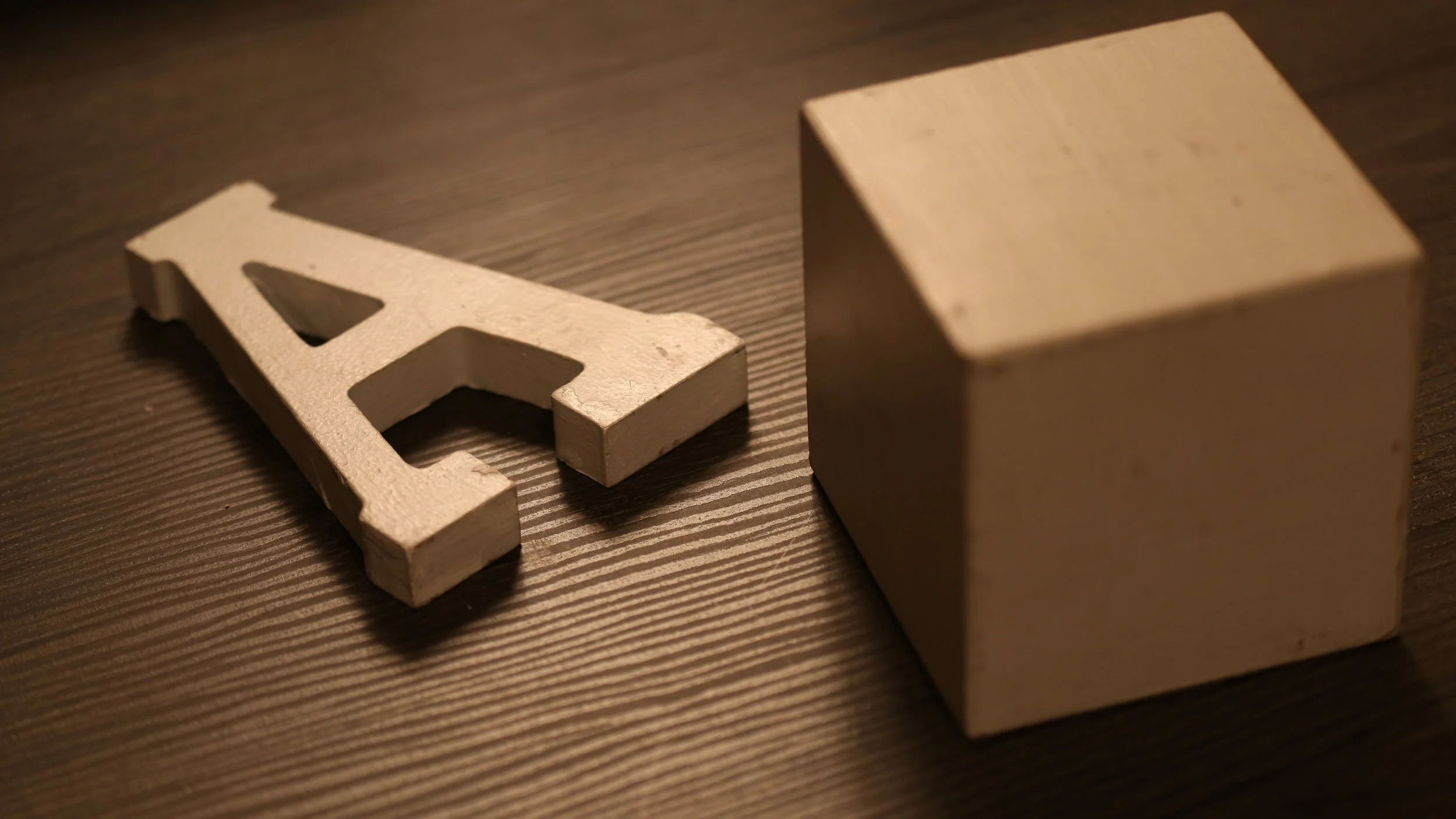
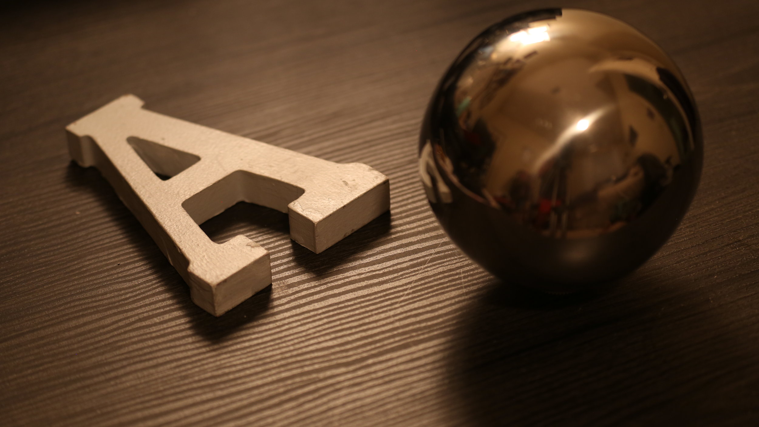
In order to provide objects to use as reference in the photos, I used a Light Integration Kit which includes: a wooden cube with square edges, a grey or white sphere, and a chrome sphere.
In the end there should be a set of atleast five photos:
A clean plate with just the object
The object and the wood cube
The object and the grey/white sphere
The object and the chrome sphere
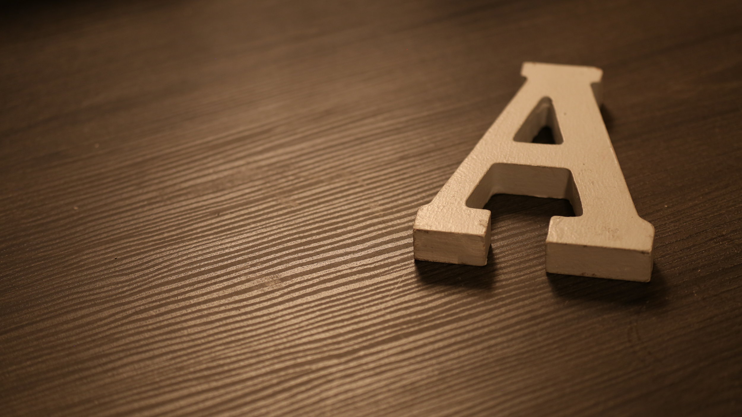
The object moved to the intended location of the CG twin
My Photos:
Camera: Canon EOS 5D Mark III
Image Size: 5760 × 3240
Color Space: RGB
Focal Length: 104
F Number: 4
Exposture Time: 1/15
Step 2: Set Up The Scene
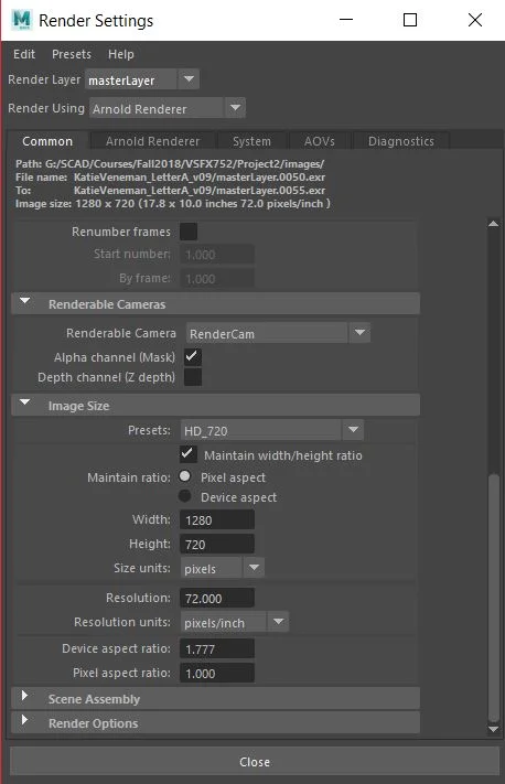
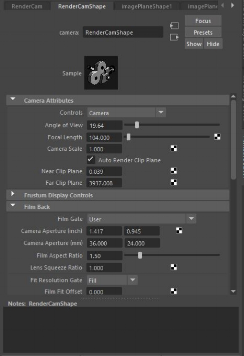
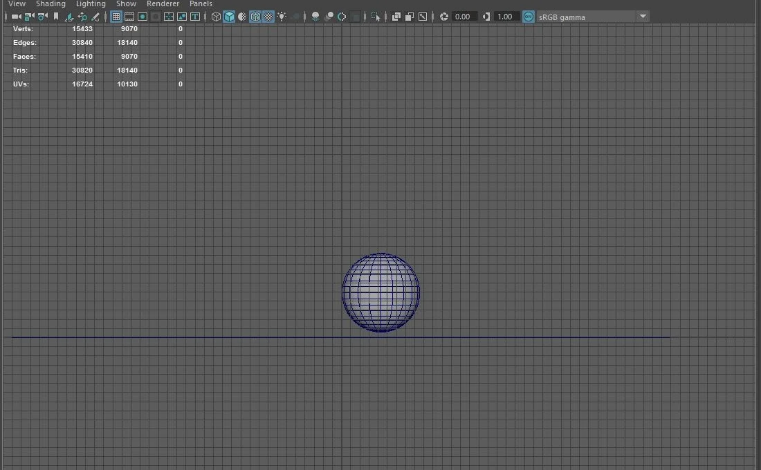
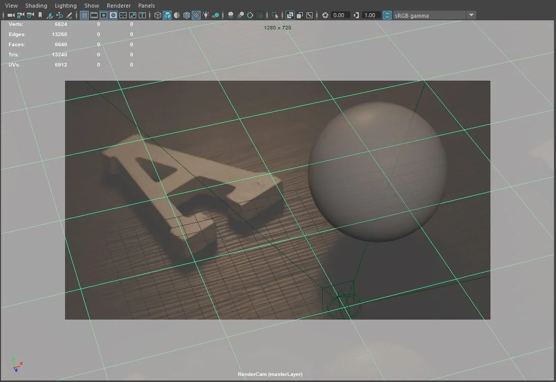
The first step in setting up my scene was to change the units in Maya to inches. Next, I looked at the image resolution of the images I took, which is 5760 x 3240. Since that is REALLY big, I scaled it down, by a multiple of the original resolution, to 1280 x 720. I then created a new camera to work with and named it “RenderCam”. Under the camera settings I changed Focal Length to match that of my photos: 104.
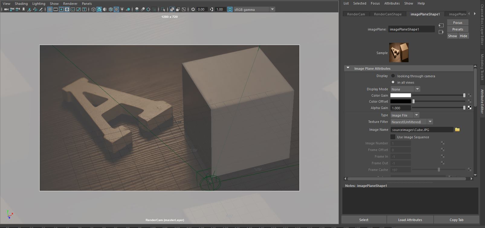
Next, under the RenderCam settings, I inserted an image plane of my object and the wood cube. I then created a cube that was approximately the same size as the cube in the photo: 3.25” x 3.25” x 3.25”. This allowed me to position my camera by moving it around until my cube lined up with that of the cube in my photo.
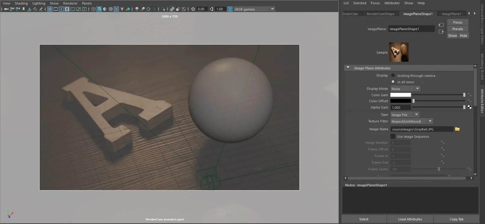
Next, I switched out the photo of the cube and put in the photo of the grey sphere on the image plane under the RenderCam. I then created a sphere that was approximately the same size of that in the photo: 1.7” x 1.7” x 1.7”. When taking the photo of the grey sphere, I had placed it on top of a bottle cap to keep it in place. So in Maya I need to move the sphere up just a little bit, to account for the size of the bottle cap.
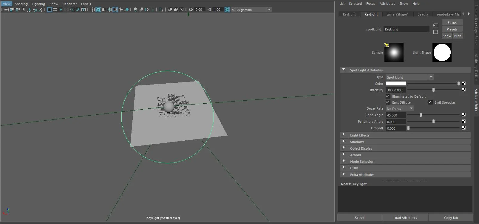
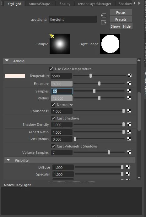
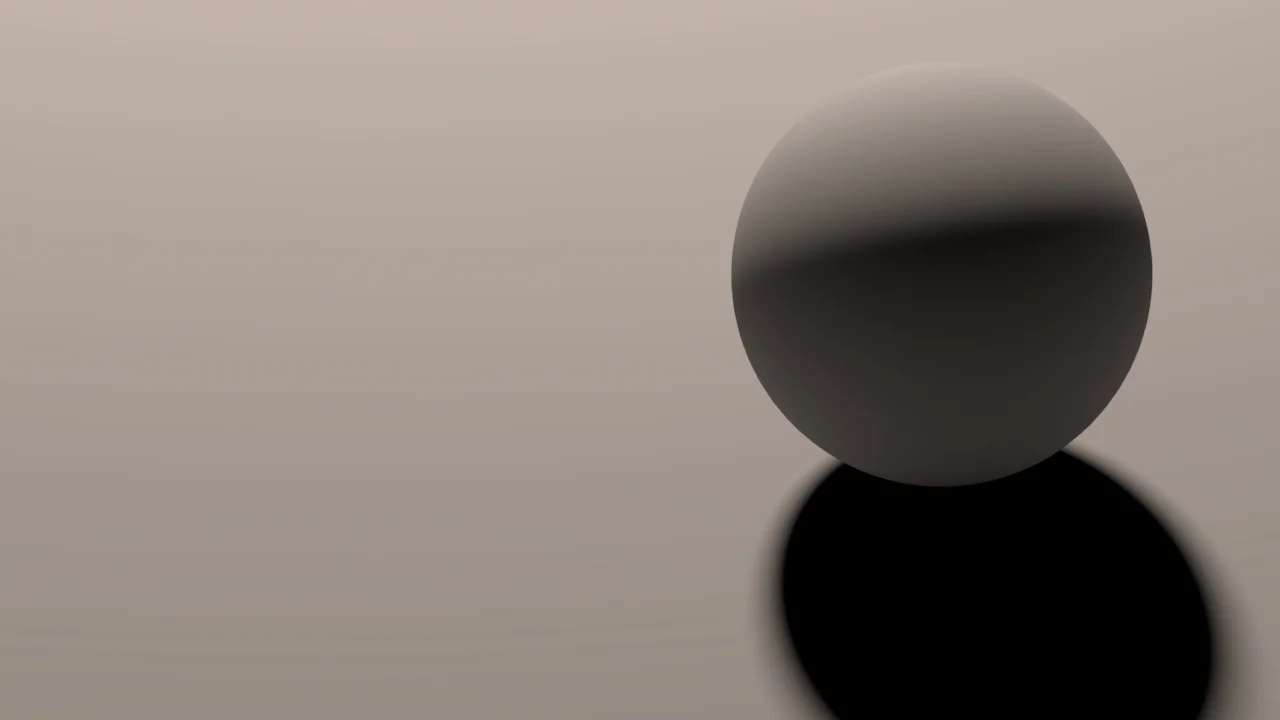
After inserting the image of the grey sphere, I can now create a Keylight and work on matching the lighting in my scene to that of the image. By paying attention to the location and softness of the shadow from the grey sphere and the specular highlights on it, I can move the Keylight around until it matches.
The next step is to prepare my image of the chrome sphere in Photoshop in order to use it as a fill light. I cropped down the image to the very edges of the chrome sphere.
Next, I created a sphere and made it large enough to fit the entire scene inside of it.
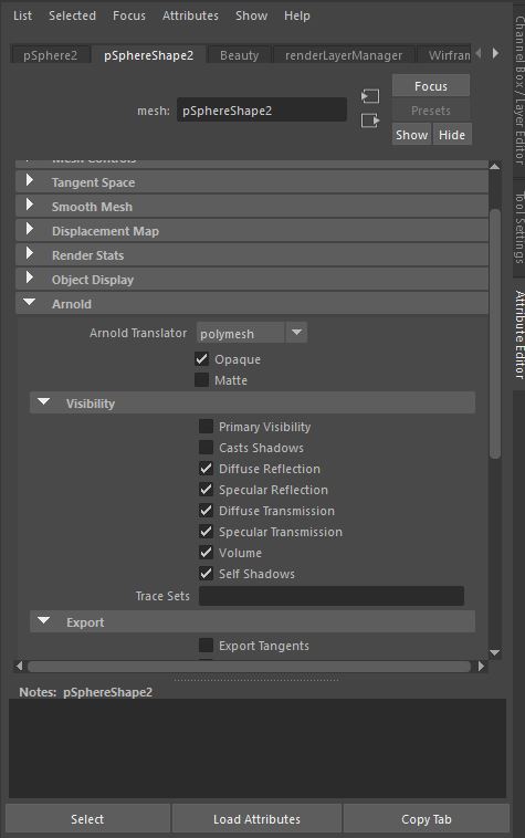
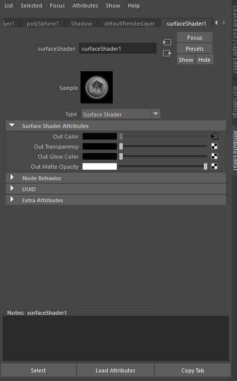
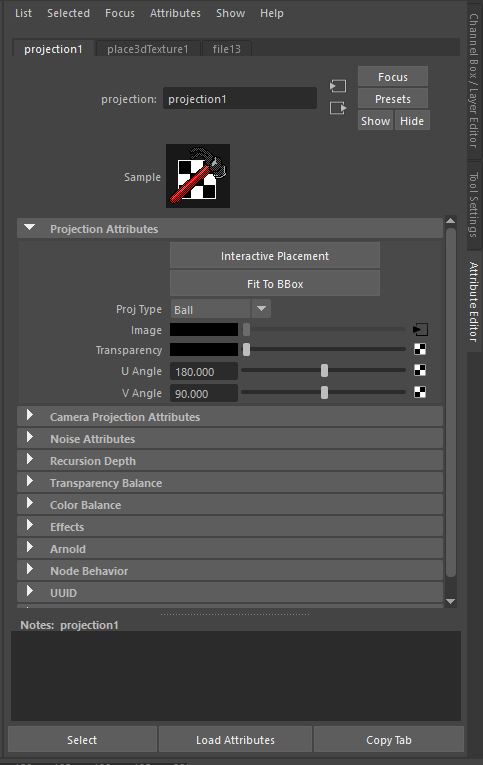
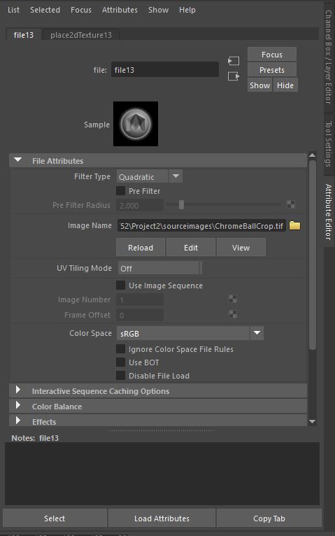
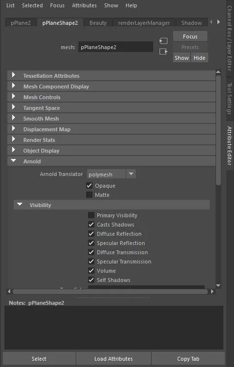
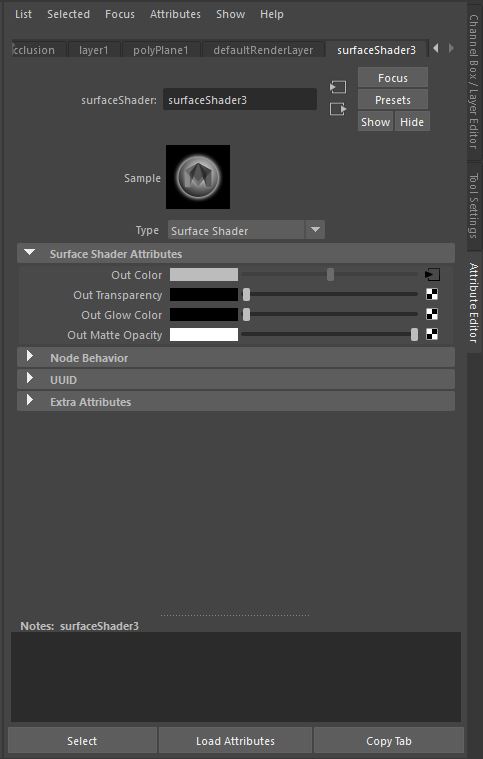
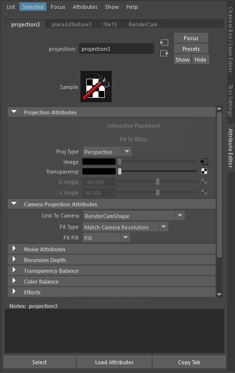
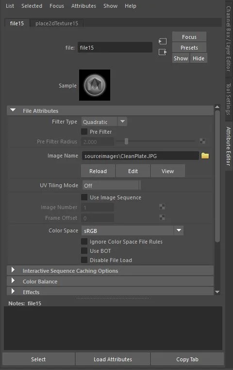
Once the sphere is created, under the Mesh tab (the second tab on the attribute editor), I went to the Arnold Settings and turned OFF Primary Visibility and Cast Shadows. Next, I assigned a new material and chose a Maya Surface Shader. Under the Surface Shader Attributes, I selected the checkerboard next to the “Out Color”, and then right clicked on the “File” option, and selected “Create As Projection”. Under the projection tab I changed the Projection Type to “Ball,” and then uploaded the image of my cropped chrome sphere.
When I render the sphere again, I now have a fill light.
The next step is to create the ground plane for the scene. This process is very similar to how I created the dome in the previous step. I created a ground plane that was large enough to fill the screen. Under the Mesh tab (the second tab on the attribute editor), I went to the Arnold Settings and turned OFF Primary Visibility. Next, I assigned a new material and chose a Maya Surface Shader. Under the Surface Shader Attributes, I selected the checkerboard next to the “Out Color”, and then right clicked on the “File” option, and selected “Create As Projection”. Under the project tab I changed the Projection Type to “Perspective,” and then went to the Camera Project Attributes. For Link to Camera I connected my “RenderCam”, and I changed the Fill Type to “Match Camera Resolution”. Lastly, I uploaded the image of my clean plate.
Step 3: Modeling and Shading the CG Object.
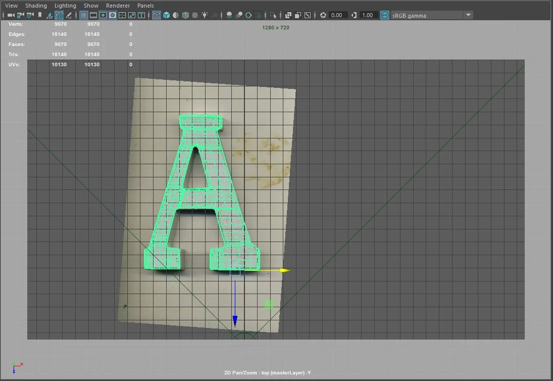
The first thing I did, before modeling or shading my twin object, was scan my Letter A on a flatbed scanner. This allowed me to important an image plane into Maya and create a texture map in order to more accurately match my model to the real object.
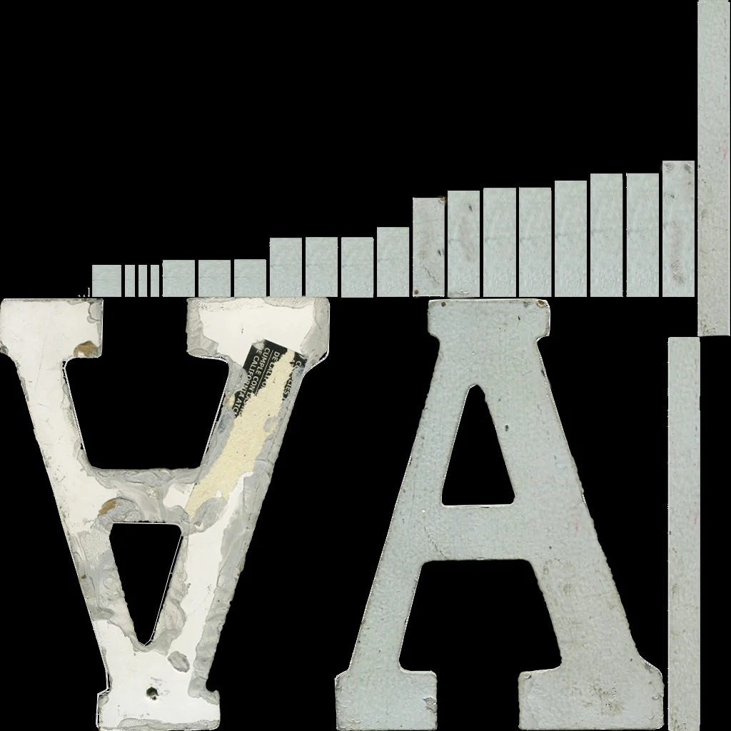
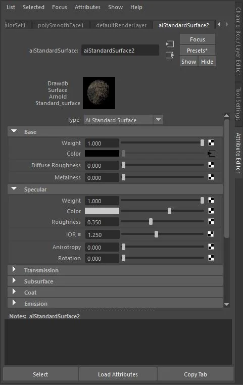
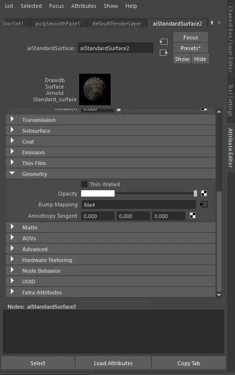
To create the Texture Map, I used the scanned images I took and placed them into the UV Layout of my letter. I then used the Clone Stamp in Photoshop to add more “imperfections” to some of the edges and top of the letter. I also added a bump map of the image on the right in order to create uneven surfaces on the geometry.
Final Shader Settings for my CG Letter A.
Step 4: Render Layers
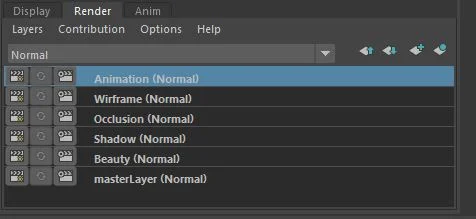
The next step is to set up separate render layers in order to be able to composite everything together in Nuke. I created the following render layers:
Beauty
Shadow
Occlusion
Wireframe
Each render layer needed to be set up in a specific way for compositing purposes.
Beauty Layer
CG Object
Key Light
Fill Light
Ground Plane with Projection of Background Plate Image, and Primary Visibility Turned Off
Occlusion Layer
CG Object with Primary Visibility Turned Off
Ground Plane with Ai Ambient Occlusion Shader (Black and White Values Switched), and Primary Visibility Turned Off
Shadow Layer
CG Object with Primary Visibility Turned Off
Key Light
Ground Plane with Ai Shadow Matte Shader, and Primary Visibility Turned On


